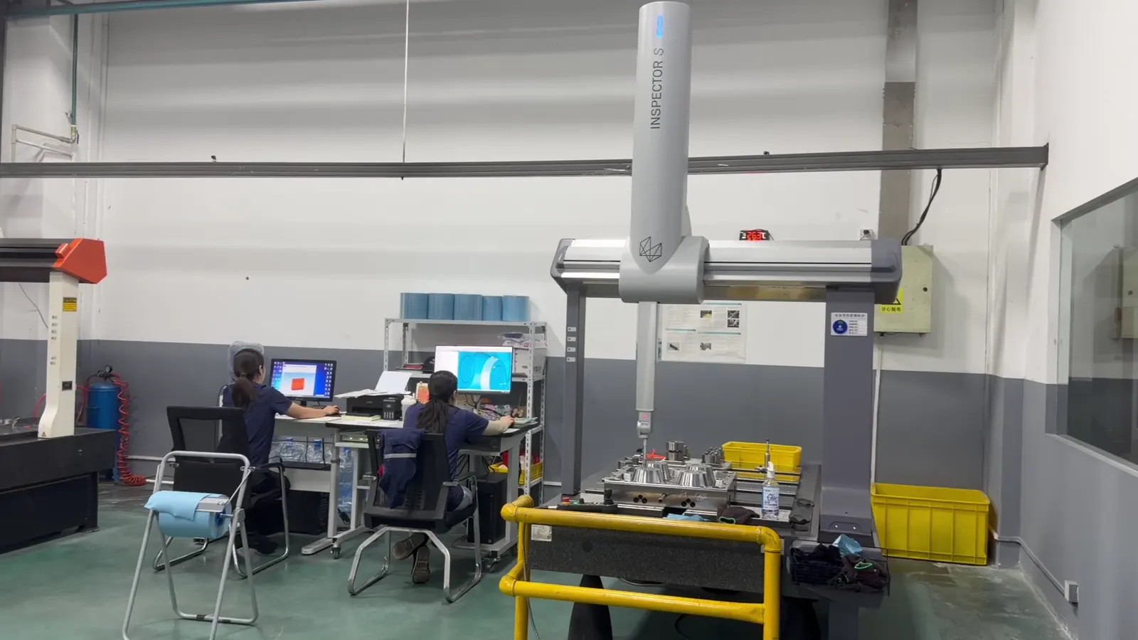
Hengqi CMM inspection room with a four-cavity mould component under probe

Functional-datum quality control

Measured before assembly. Stable in production.

Inspection follows the component relationships that make an IML or thin-wall mould fit, move, seal and repeat—not only isolated dimensions on a report.

CADNominal comparison
Before assemblyCritical relationship check
FunctionalDatum-based planning
DocumentedFeedback to engineering

Visual engineering record

See the people, decisions and production stages behind the claim.

Each section links a real Hengqi image with the engineering purpose it supports. Buyers can understand what is reviewed, what is manufactured and what evidence is checked before delivery.

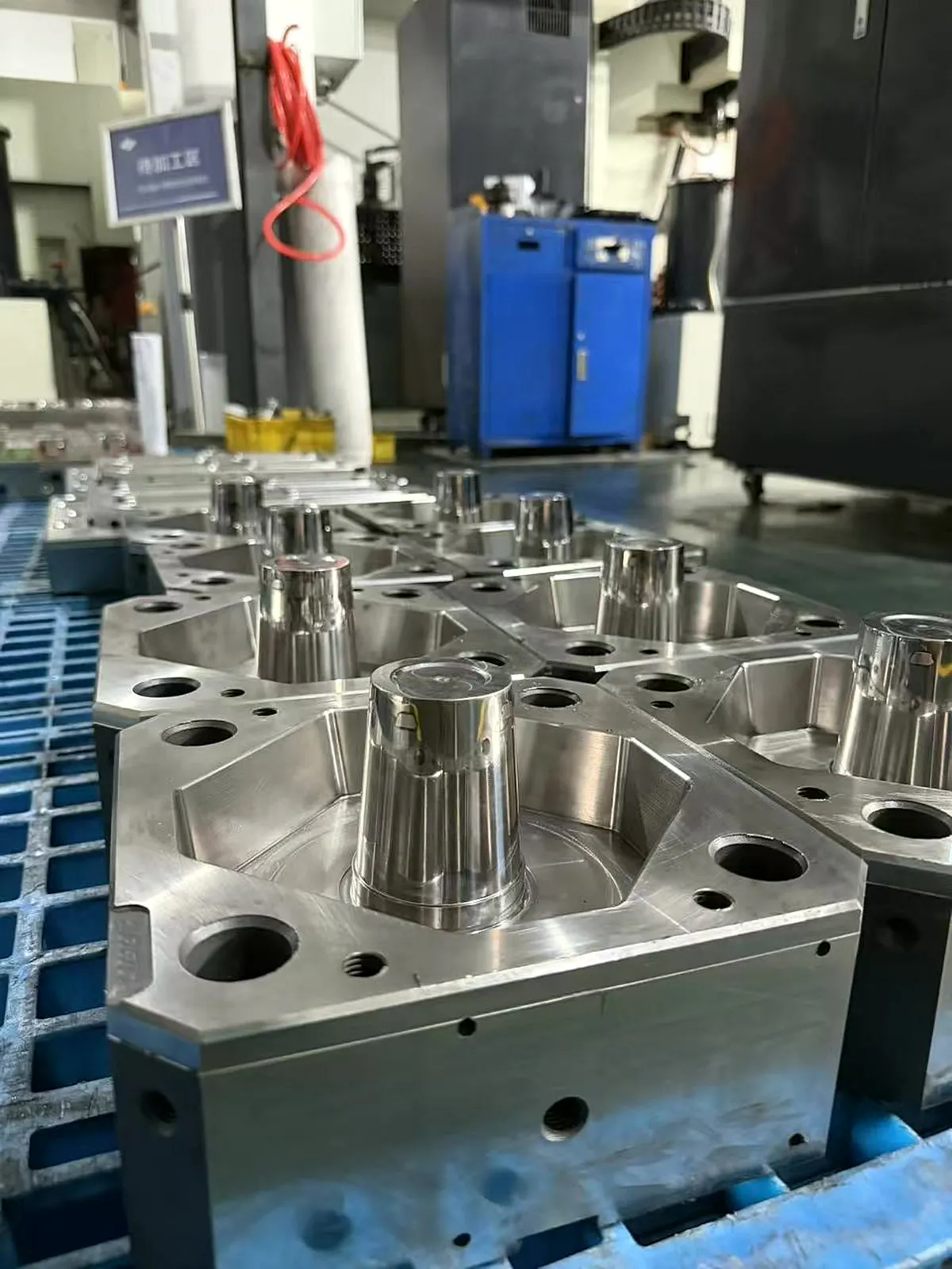
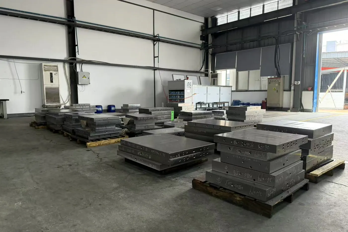
Mould-base plates prepared around controlled reference faces
Datum foundation · mould-base relationships established before later operations

01 / Inspection planning

Measurement starts by defining what makes the assembly function.

The inspection route is built around the product, mould structure and approved functional datums.

Critical positions, profiles, flatness, perpendicularity, distances and mating relationships are selected according to their role in the mould.

  • Functional datum definition
  • Project-specific inspection plan
  • Nominal and tolerance requirements
Finished mould cores and inserts ready for dimensional verification
Critical components · geometry reviewed in its assembly context

02 / Working components

Selected parts are measured according to their function in the mould.

Cores, cavities, inserts, sliders, wear plates, locating blocks and shut-off features do not carry equal risk.

Inspection attention is concentrated where positional error or profile deviation could affect assembly, movement, sealing, wall thickness or product release.

  • Core and cavity geometry
  • Insert and slider position
  • Mating and shut-off relationships
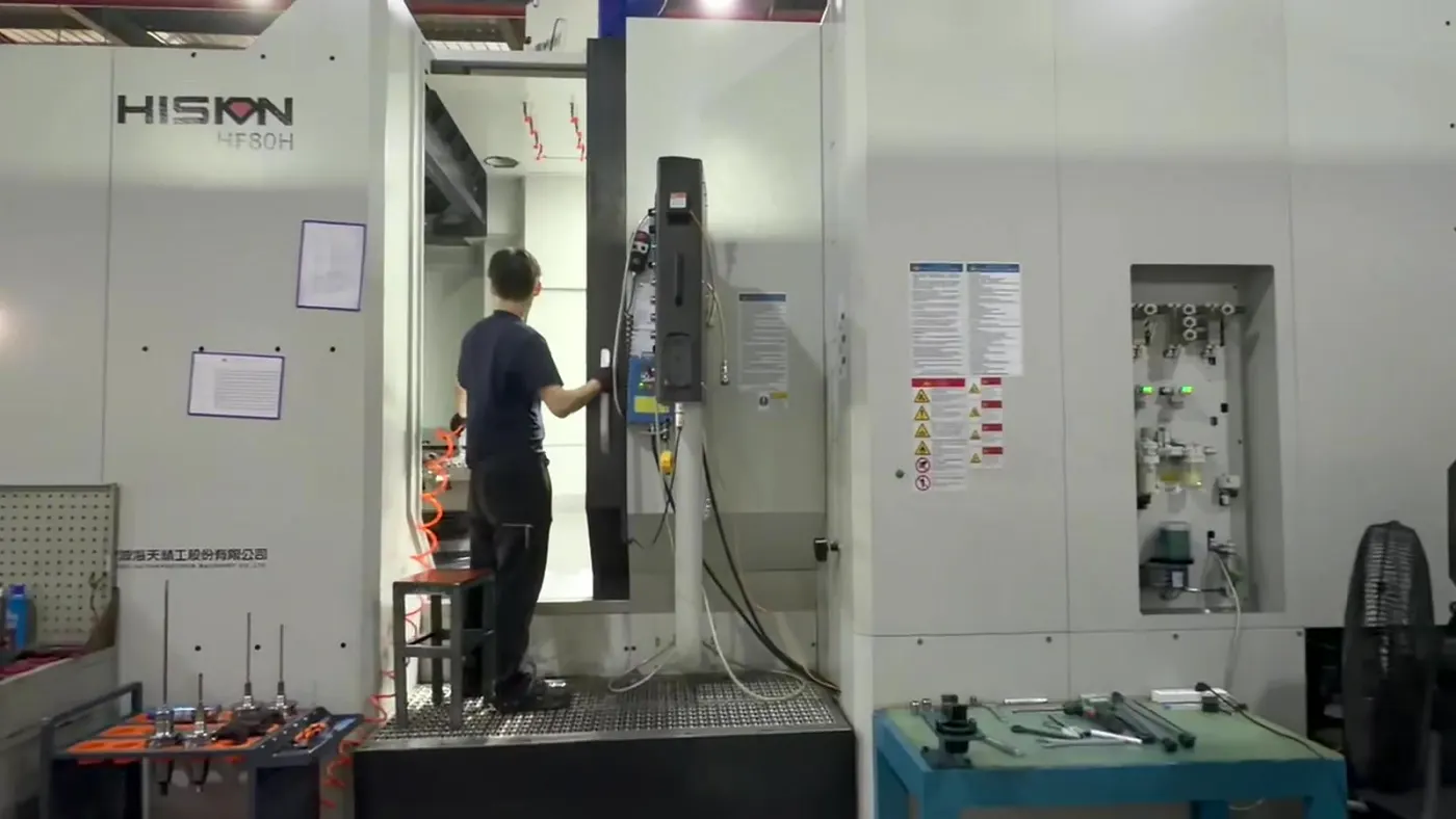
Five-axis mould machining stage connected to dimensional feedback
Closed manufacturing loop · measured findings returned to the responsible process

03 / Machining feedback

Measurement is useful when it closes the manufacturing loop.

Results are compared with the approved CAD model and tolerance plan, then returned to the responsible manufacturing stage.

This makes inspection an engineering feedback channel, allowing correction before the component becomes buried inside final assembly.

  • CAD-to-actual comparison
  • Deviation reviewed by function
  • Correction before final fitting
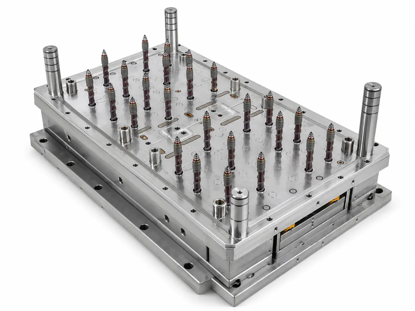
Complete mould assembled after component inspection
Assembly release · component relationships brought into one functional system

04 / Assembly gate

High-precision assembly starts before parts reach the bench.

Verified datums and mating interfaces give the assembly team clearer evidence about fit and alignment.

Assembly findings are recorded against design intent so corrective work remains traceable instead of becoming undocumented bench adjustment.

  • Fit and alignment evidence
  • Cooling and hot runner interfaces
  • Traceable assembly feedback
IML yoghurt cup sample used for mould trial validation
Trial sample · product evidence linked back to mould geometry and process

05 / Production validation

The product result provides the final check on the measurement plan.

Trial samples reveal whether the controlled geometry supports filling, wall distribution, sealing, stacking, label placement and ejection.

Product measurements and cavity comparisons are reviewed with the mould and process condition before final release.

  • Product dimension review
  • Cavity-to-cavity comparison
  • Acceptance evidence before delivery

Real inspection evidence

See the equipment, component setup and engineering review behind the measurement result.

These images were recorded in Hengqi's inspection room. They show how an actual mould component is fixtured, probed and compared with the released CAD data before an engineering decision is made.

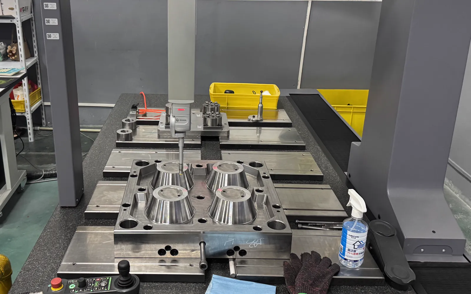
Close view of CMM probe measuring a four-cavity mould component
Real component setup · probe access planned around mould function

01 / Component setup

The probe follows the functional geometry of an actual mould component.

A four-cavity mould component is positioned on the granite table with the probe working directly around the formed surfaces and reference features.

The setup is planned around the features that influence assembly, wall distribution, alignment and repeatable product geometry—not around a generic inspection demonstration.

  • Functional datum selection
  • Controlled fixture and probe access
  • Critical profile and position review
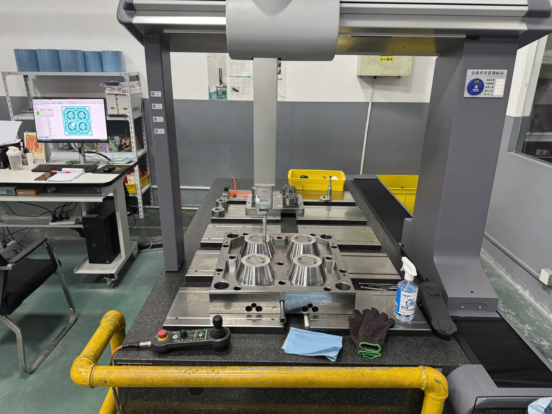
Hengqi inspectors reviewing CAD data beside the CMM
Inspection review · physical measurement connected with CAD intent

02 / Inspection team

Measurement stays connected to the released CAD model.

Inspectors work beside the measuring equipment so the physical feature and its digital nominal can be reviewed together.

Unexpected deviation is assessed by function and returned to engineering, machining or fitting before the component is released.

  • CAD nominal comparison
  • Deviation review
  • Traceable feedback
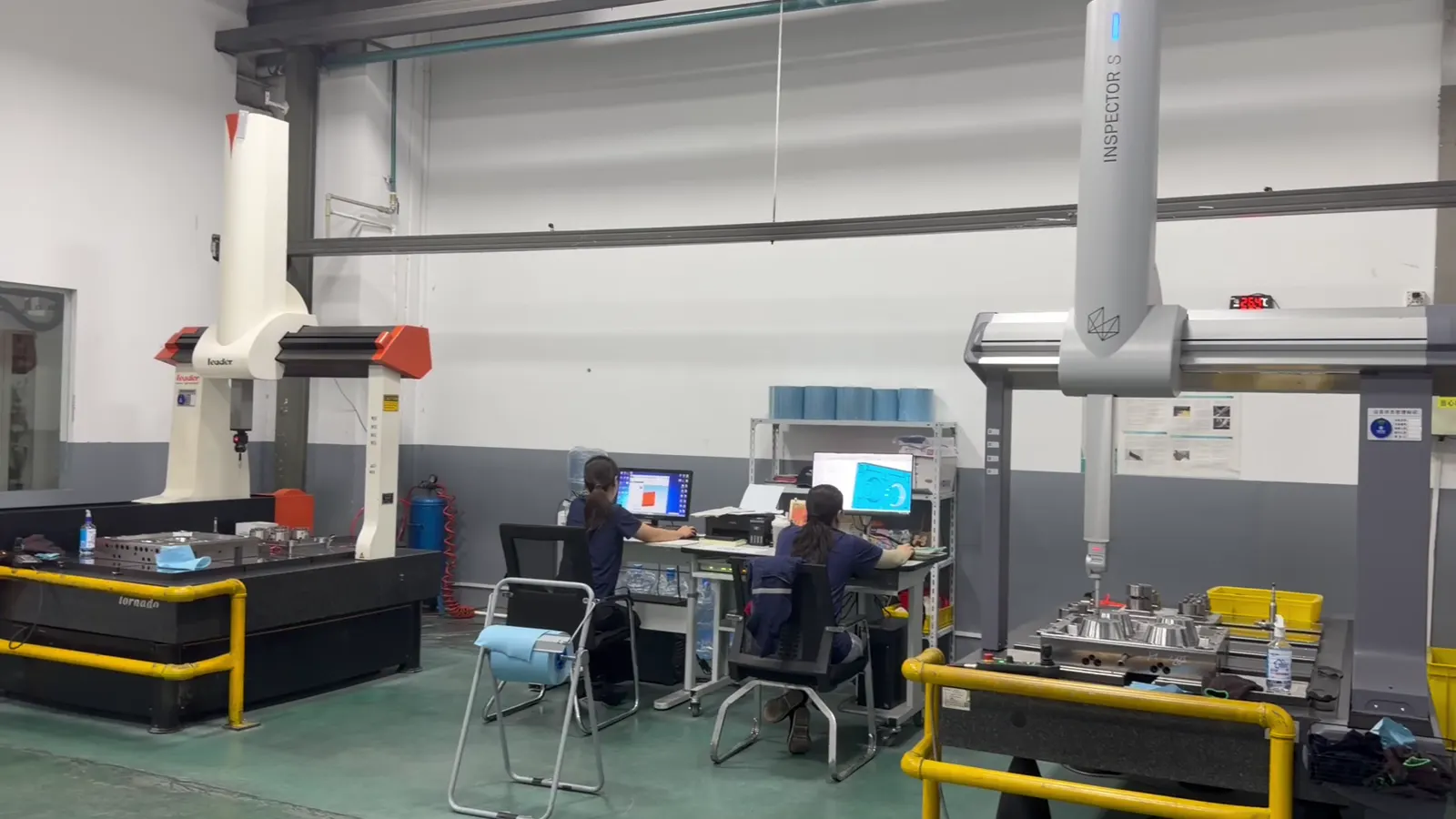
Two CMM systems and inspectors in Hengqi's measurement room
Inspection room · equipment and review stations in one controlled workflow

03 / Inspection capacity

Parallel equipment supports component and assembly-focused checks.

The inspection room provides space for mould plates and components while technicians prepare programs and review results beside the machines.

The exact measurement scope and buyer-facing report are agreed for each project so the evidence matches the approved acceptance plan.

  • Mould component capacity
  • Project-specific scope
  • Agreed report output

Measurement workflow

From physical geometry to a clear engineering decision.

The inspection loop protects the relationships that influence mould assembly and repeatable production.

01

Define

Identify the functional datum, feature risk and approved tolerance requirement.

02

Measure

Probe or verify the selected geometry with the appropriate inspection method.

03

Compare

Review actual results against CAD, tolerance and assembly context.

04

Respond

Return findings to machining, fitting or engineering before release.

Start with the production requirement

Define the inspection evidence while the mould is being planned.

Inspection scope, reports and acceptance points should be agreed before final machining and trial.

Send project information
01Approved product and mould drawings
02Critical dimensions and tolerance requirements
03Mating, shut-off and moving interfaces
04Buyer-specific report or format requirements
05Product sample inspection requirement
06Pre-shipment acceptance and documentation list

Buyer questions

Clarify the project before steel is committed.

Which mould parts are selected for detailed dimensional inspection?

The inspection plan focuses on project-specific functional parts such as cores, cavities, inserts, sliders, locating features, shut-offs, wear interfaces and assembly-critical datums.

Why is measurement completed before final assembly?

Checking critical component relationships before fitting helps prevent positional, shut-off and alignment problems from being discovered only after the mould is assembled.

Can inspection records be included with delivery?

Required reports and documentation should be agreed during project review. Hengqi can define the measurement scope and delivery records around the approved acceptance plan.